Engineering Projects
Hardware Prototyping • Arduino • Controls Concepts • Resin Printing • Research Fabrication
This page documents my hardware-focused engineering projects, including an Arduino-based bicopter experiment and an inverted pendulum prototype. These projects combine mechanical design, electronics integration, additive manufacturing, testing, documentation, and physical presentation.
 Home
Home Engineering Projects
 CGI
CGI Faelestial Archive
 Research Manuscript
Hardware Engineering & Research
During my time at UC Merced, I worked on hardware projects that introduced me to embedded systems, experimental testing, controls concepts, and the challenge of connecting physical hardware with software and electronics.
My strongest contributions were in mechanical design, prototype fabrication, resin printing, visual presentation, hardware assembly, and documentation. I treated these projects not only as technical exercises, but also as finished physical artifacts that could communicate engineering development clearly.
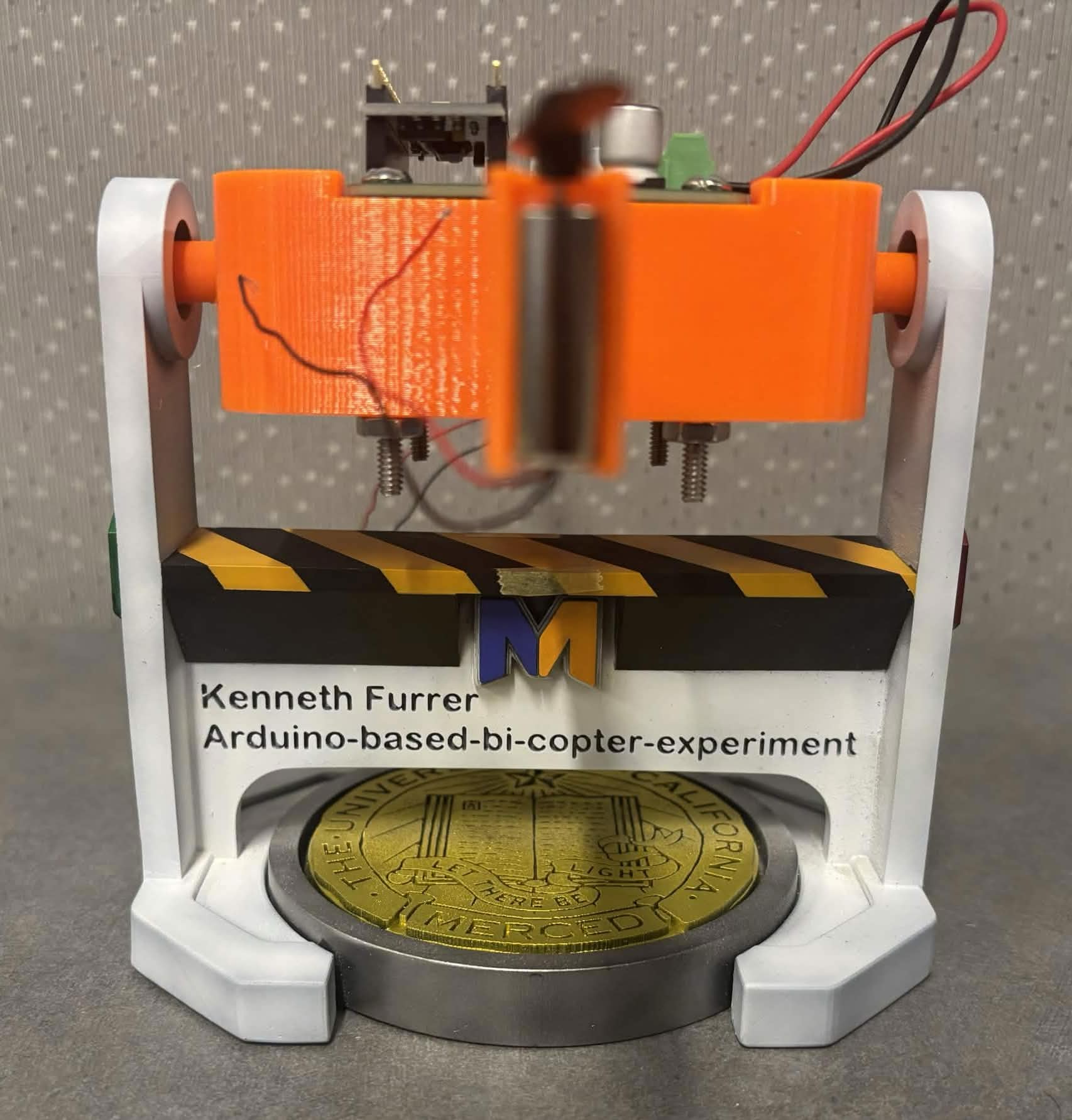
Arduino Bicopter
A two-rotor experimental platform used to explore open-loop behavior, closed-loop feedback, PID tuning concepts, mechanical design, and prototype fabrication.
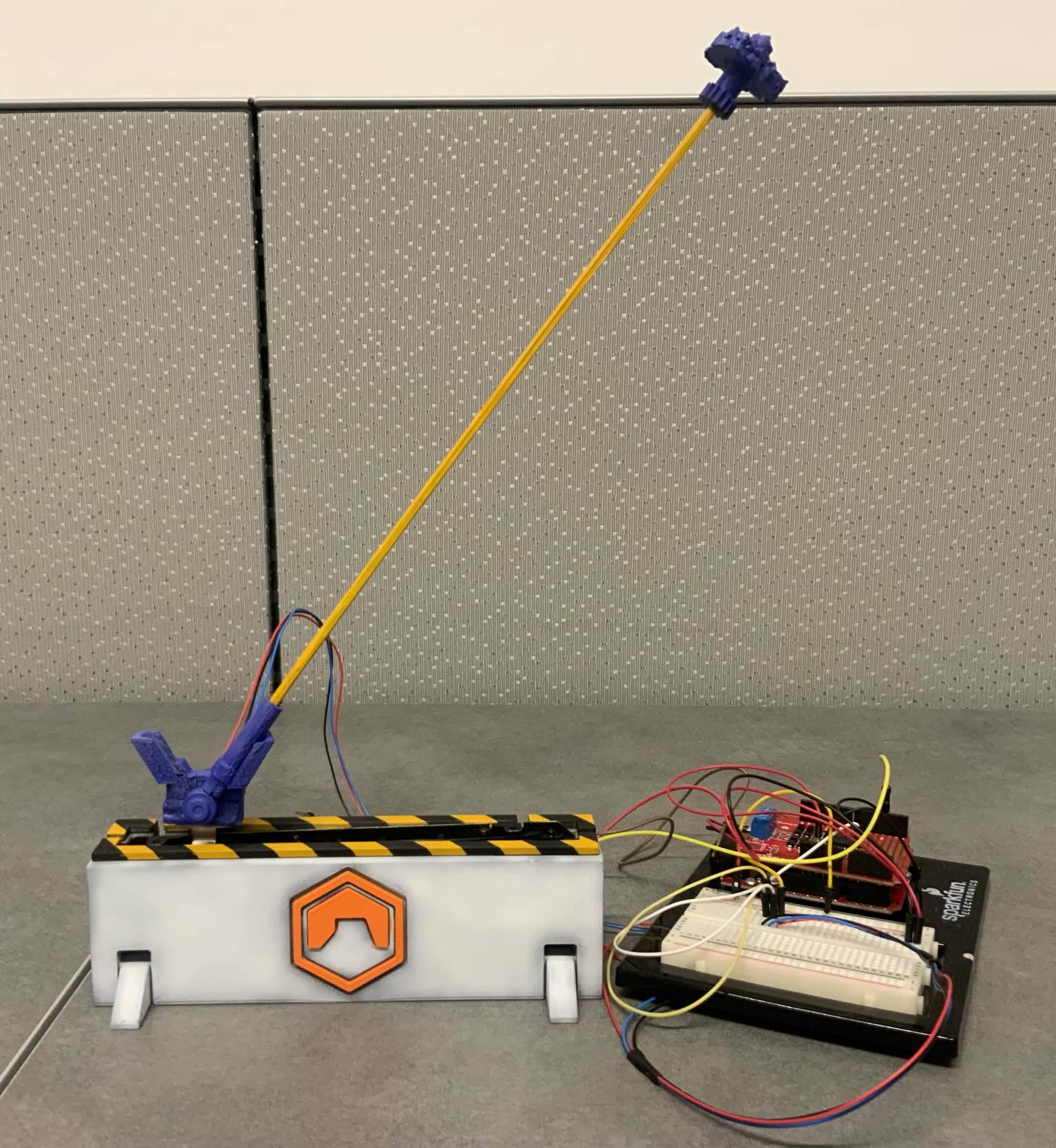
Inverted Pendulum
A hardware control project involving an unstable balancing system, Arduino electronics, MATLAB/Simulink experimentation, and custom mechanical presentation.
Arduino-Based Bicopter Experiment
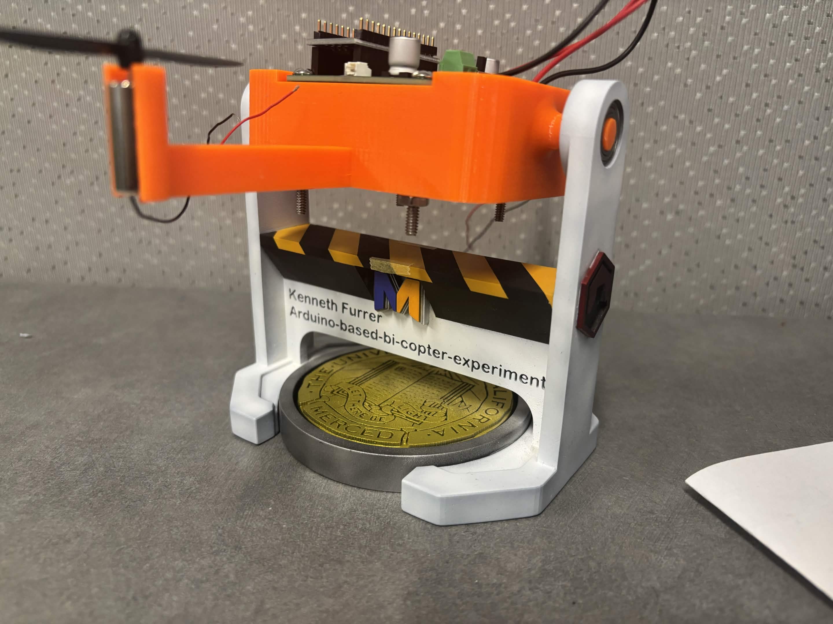
Finished Arduino-based bicopter prototype mounted on a custom resin-printed research stand.
Project Overview
The Arduino-based bicopter experiment explored the behavior of a two-rotor stabilization system. The project introduced me to the challenge of balancing thrust, reading sensor feedback, adjusting motor response, and observing how unstable systems behave during testing.
This project connected several parts of engineering into one physical prototype: mechanical structure, electronics, software, motor behavior, feedback control, fabrication, documentation, and final presentation.
Research Environment & Presentation
Both the Arduino Bicopter and Inverted Pendulum projects were developed during my undergraduate research experience in the Mechatronics, Embedded Systems and Automation (MESA) Lab at the University of California, Merced.
Rather than mounting the hardware to simple wooden bases or temporary fixtures, I designed custom resin-printed display stands for both projects. To acknowledge the laboratory where the research was conducted, each stand features the official MESA Lab logo together with custom project labeling and presentation details.
Every stand was modeled in CAD, resin printed, sanded, painted, and assembled as part of the overall project. Beyond supporting the hardware mechanically, the stands were designed to present each prototype as a professional research display for demonstrations, documentation, and photography.
Both the Arduino Bicopter and Inverted Pendulum prototypes featured throughout this page were developed while conducting undergraduate research in the UC Merced MESA Lab.

MESA Lab
Mechatronics, Embedded Systems and Automation
University of California, Merced
The research laboratory where both hardware projects were completed.
Open-Source Foundation
This project was developed while learning from the open-source Arduino-based Bi-Copter Experiments repository created by Dr. Eniko T. Enikov. The repository provides a foundation for learning bicopter hardware, Simulink models, system identification, and introductory control-system design.
I used the repository as a learning and practice reference while building the physical hardware platform. My work focused on fabrication, assembly, visual presentation, stand design, resin printing, painting, documentation, and integrating the prototype into a polished engineering display.
My Contributions
Rather than presenting the bicopter as a project I invented from scratch, I describe it as an open-source-based engineering build that I customized, fabricated, assembled, and documented. This separates the original project foundation from my personal design and fabrication work.
Design, Fabrication & Presentation Workflow
A major part of the bicopter project was transforming the hardware from a temporary electronics setup into a finished research display. This workflow documents the path from digital design to resin printing, painting, labeling, and final presentation in the engineering workspace.
Digital Design
The stand was modeled digitally with support features, side walls, a display base, project text, and MESA Lab identity integrated into the physical form.
Resin Printing
Resin printing allowed the stand to capture fine details, sharp lettering, and smooth surfaces that were difficult to achieve with rougher fabrication methods.
Finishing
The final presentation required sanding, painting, masking, reverse wash techniques, decals, hazard striping, and careful cleanup before assembly.
Mechanical Design & Stand Customization
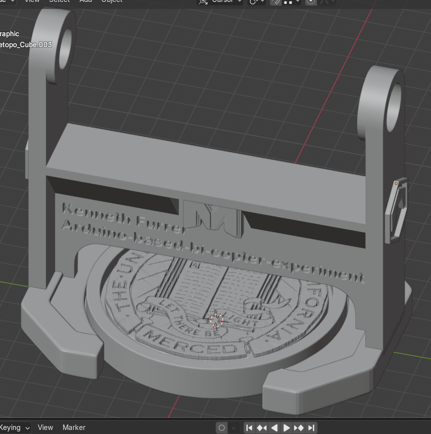
Blender Stand Design
Blender viewport showing the custom stand model, engraved project text, MESA Lab logo placement, and overall display structure before printing.
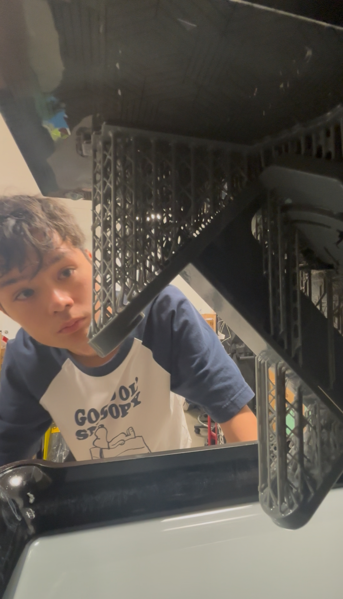
First Print Inspection
Inspecting the resin print directly on the build plate to check support placement, print quality, and whether the stand details formed correctly.
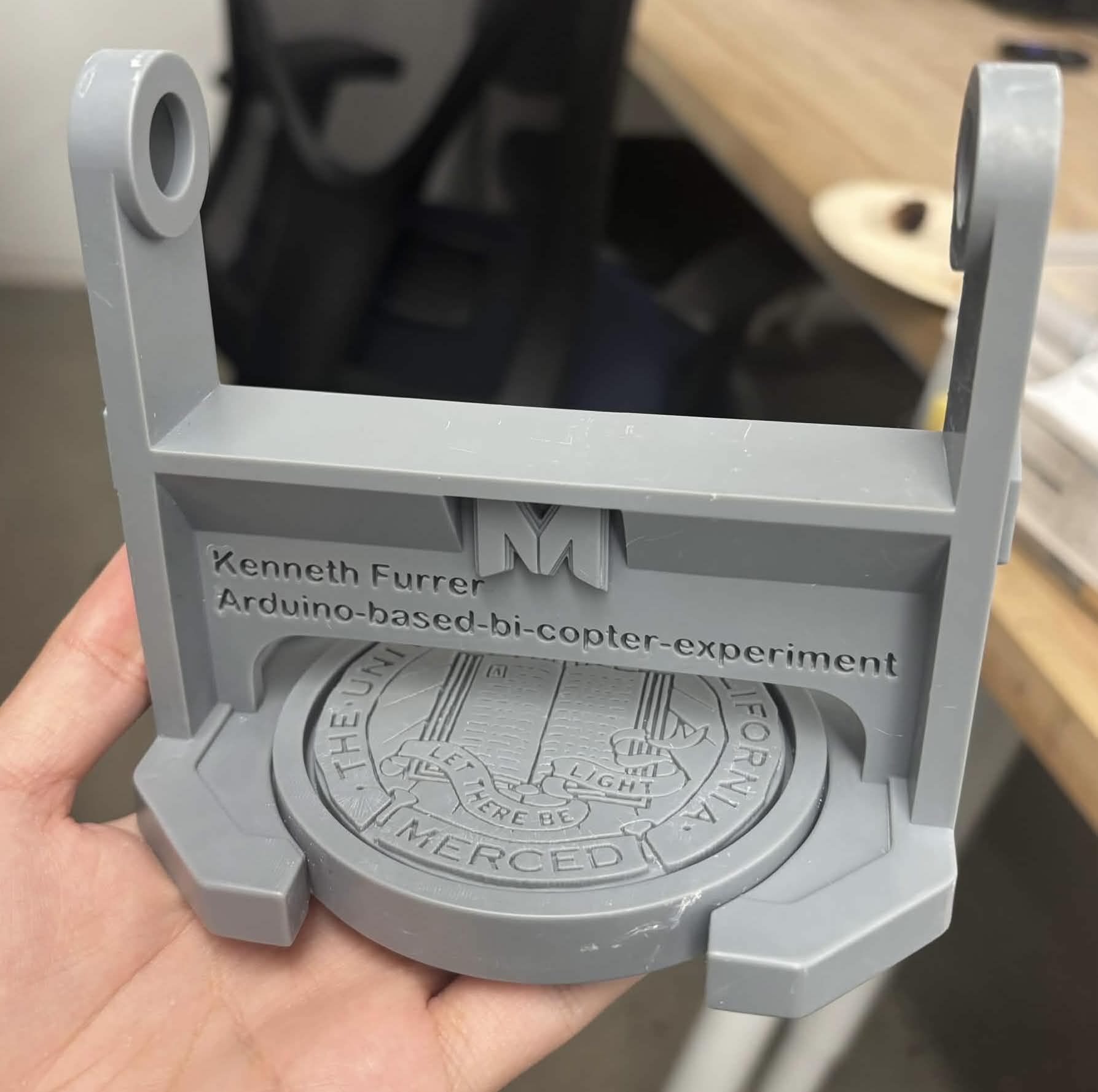
Raw Resin Print
Fresh resin-printed stand before sanding, painting, and final finishing.
Phase 1 — Painting Process
The stand received multiple airbrushed layers including black primer, white base coat, metallic red and green MESA side accents inspired by aircraft navigation lights, metallic gold for the UC Merced seal, metallic silver trim, and the primary project colors before final curing.
Phase 2 — Masking & Detail Finishing
Protective masking was carefully removed to reveal the painted surfaces. Additional detailing followed, including hazard stripes, the rear MESA Lab logo, airbrush touch-ups, and final color corrections before weathering.
Phase 3 — Reverse Wash Technique
The MESA Lab logo and engraved lettering were enhanced using a reverse wash technique. Enamel paint was applied over the details and selectively removed with lighter fluid to improve contrast while preserving the painted surface underneath.
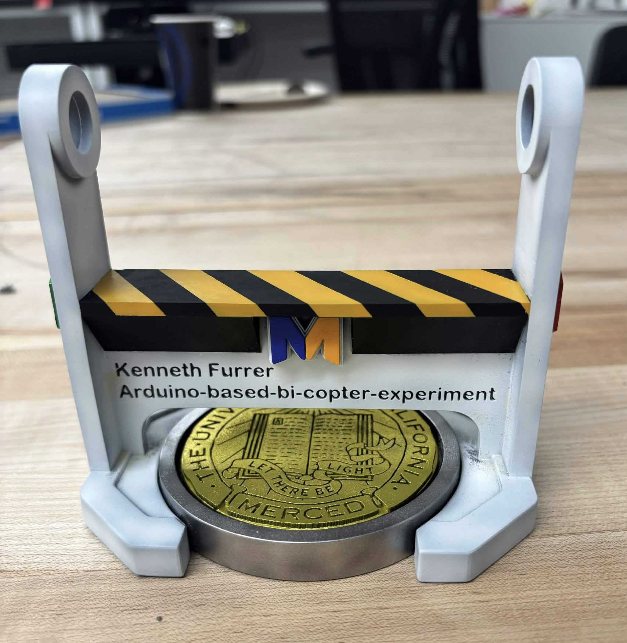
Painted Finish
Paint, hazard striping, MESA Lab identity, and display details were added to make the prototype feel like a finished research object.
Final Assembly
The completed stand was carefully assembled using protective masking to prevent paint damage while installing the bicopter hardware. The final inspection marked the completion of the fabrication process before the prototype was prepared for documentation and presentation.
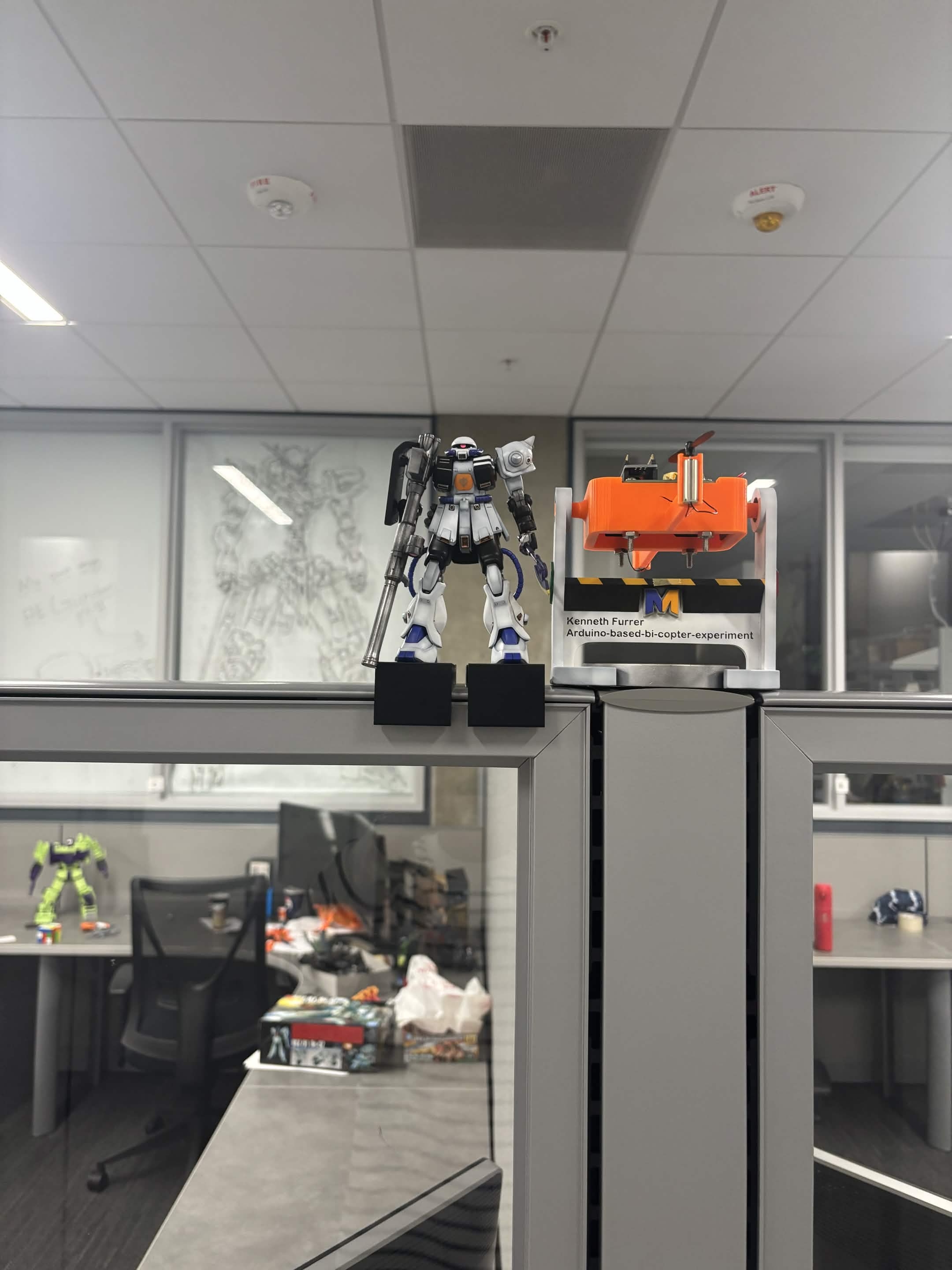
Engineering Workspace
The completed bicopter prototype displayed at my research cubicle on the third floor of UC Merced's Science and Engineering building, in the Mechanical Engineering and Aerospace research area.
The stand was one of the most important parts of the project visually. I wanted the final prototype to communicate engineering effort immediately, even before someone looked closely at the electronics or control system. The custom base helped organize the mechanism, reduce visual clutter, and give the project a stronger research-display identity.
Fabrication Timelapse
Timelapse documenting painting, masking, decal application, reverse wash cleanup, and final finishing work on the bicopter display stand.
Bicopter Hardware, Electronics & Control Practice
After the mechanical display was completed, the project continued as a hardware integration exercise involving Arduino electronics, motors, sensor feedback, MATLAB/Simulink deployment, and introductory control concepts.
Feedback from the Original Project Author
While building the bicopter, I contacted Dr. Eniko T. Enikov, the creator of the open-source Arduino-based bi-copter experiments, for help troubleshooting Arduino Nano 33 IoT and MATLAB/Simulink deployment issues. His reply included technical suggestions about Wi-Fi networks, COM ports, firmware, and MATLAB support packages.
In the same reply, he also commented on the physical build: “Nice print of the bicopter by the way!” This feedback was meaningful because the custom stand, resin printing, finishing, and research-style presentation were the parts of the project I most personally designed and refined.
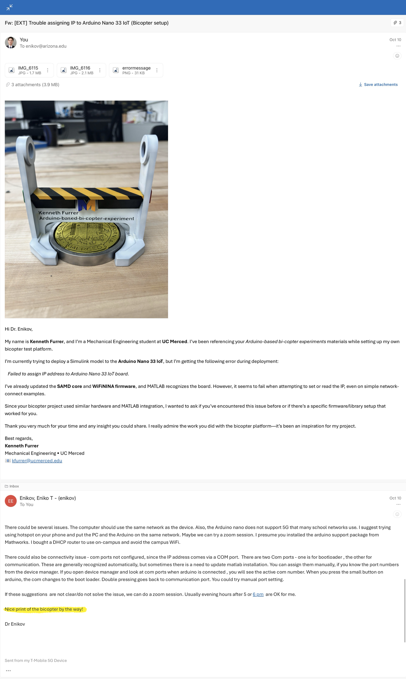
Screenshot of email feedback from Dr. Enikov. Add a cropped screenshot of the message here, especially the line complimenting the bicopter print.
Electronics & System Integration
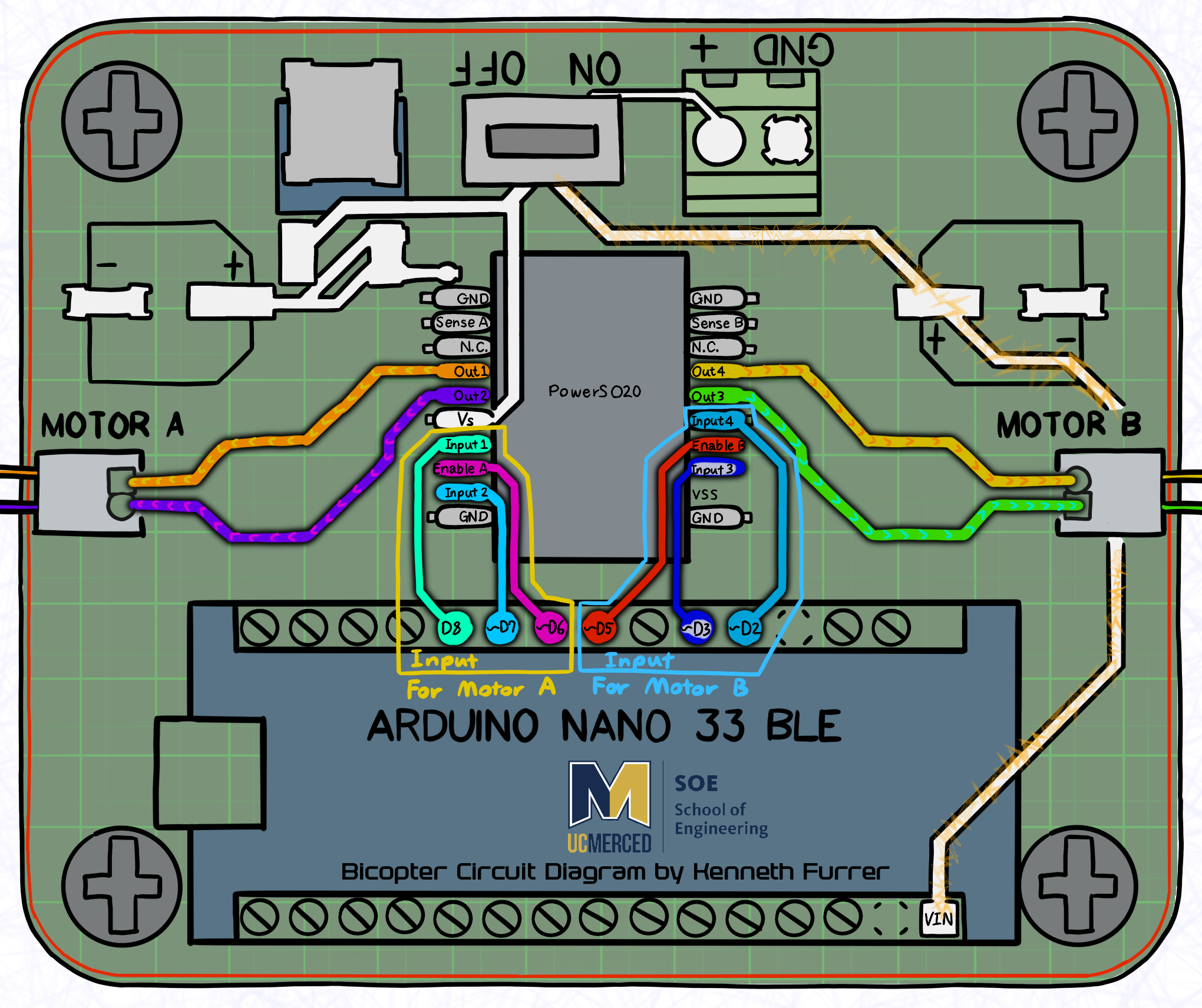
Arduino Electronics
Arduino-based wiring and electronics setup used to drive the bicopter and support experimental control testing.
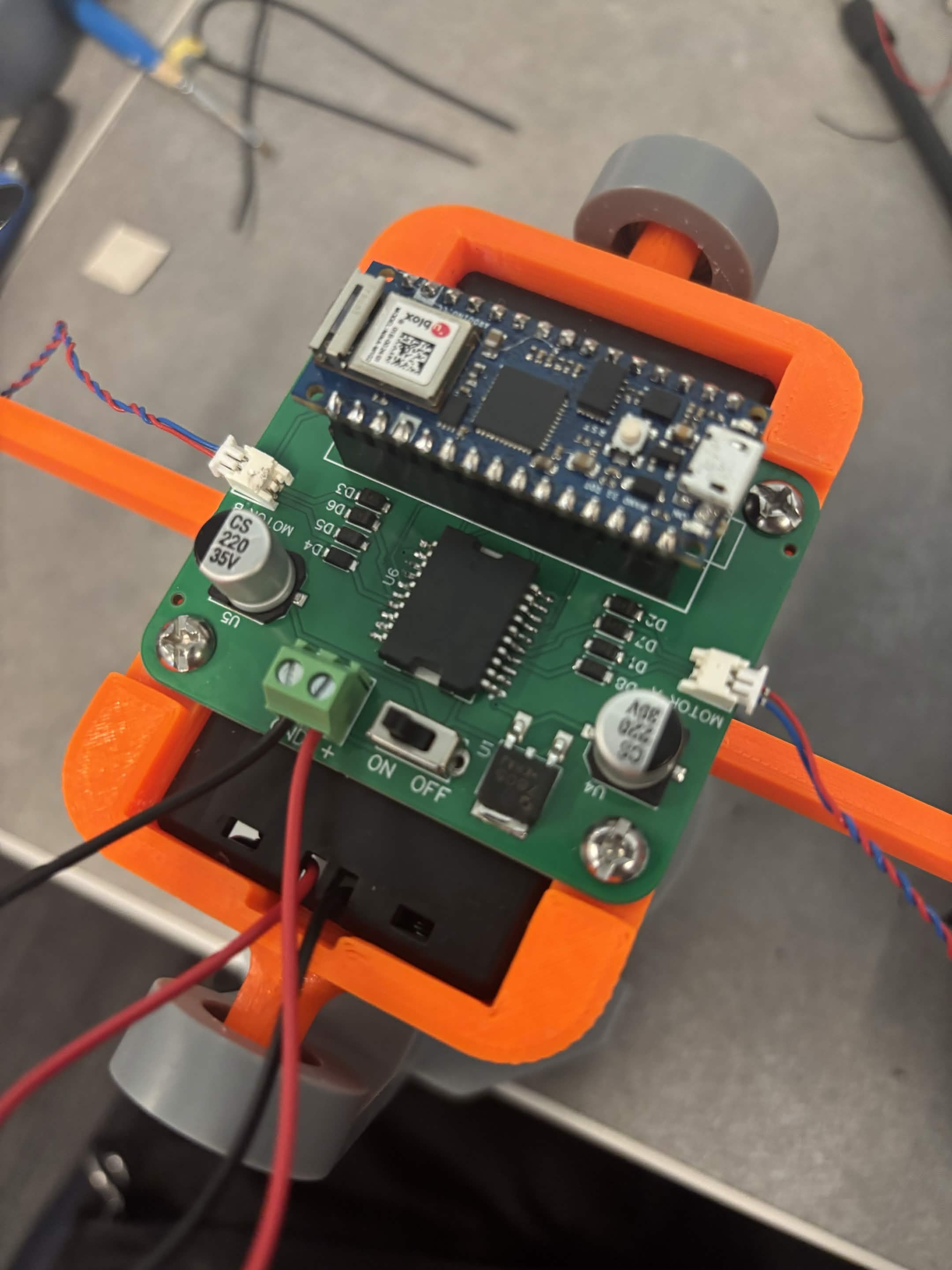
Motor Assembly
The two-rotor configuration required careful physical setup so thrust, balance, and sensor behavior could be observed during testing.
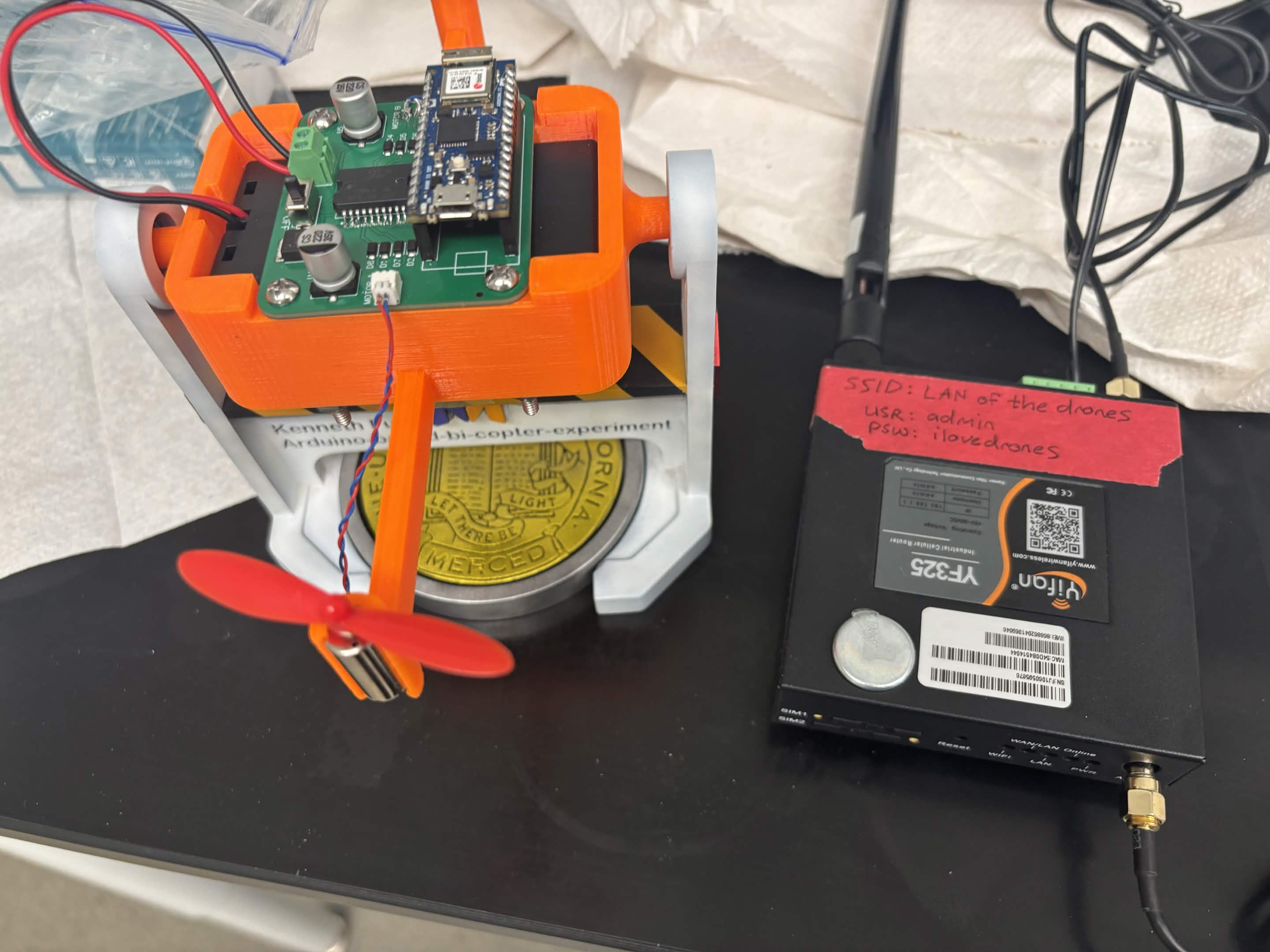
Testing Setup
The prototype was tested while observing response behavior, oscillation, stability, and the effect of different control adjustments.
Control Concepts
This project introduced me to the difference between open-loop and closed-loop systems. In open-loop behavior, the system responds based on input without correcting itself using feedback. In closed-loop behavior, sensor feedback is used to adjust the output and reduce error over time.
I also experimented with PID tuning concepts. The proportional term reacts to current error, the integral term responds to accumulated error, and the derivative term responds to the rate of change. Tuning these values showed me how easily a real physical system can oscillate, overcorrect, or become unstable.
I do not present this project as deep controls expertise. Instead, it represents hands-on exposure to real control-system difficulty and the process of learning through testing, adjustment, and documentation.
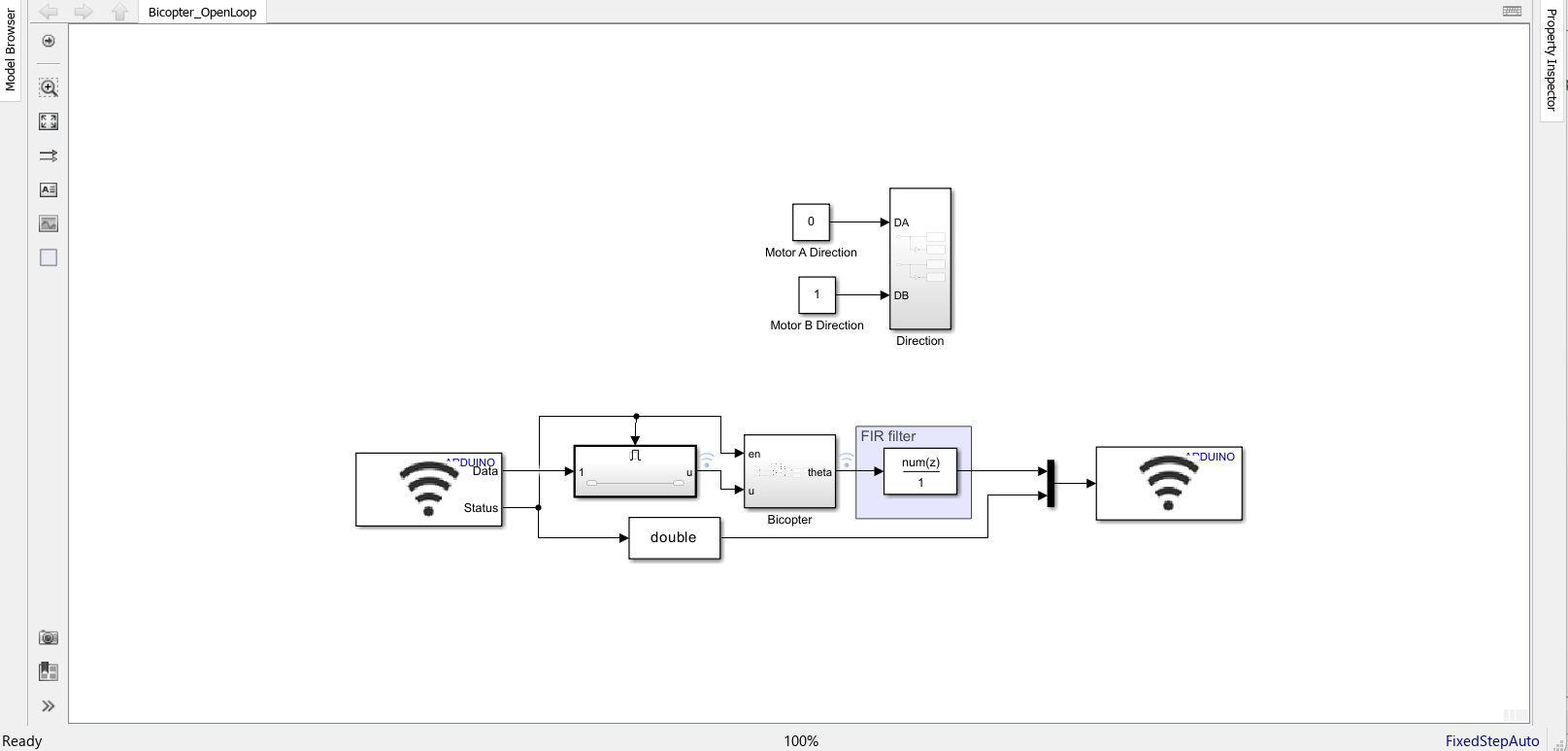
MATLAB / Simulink
MATLAB and Simulink screenshots showing controller development, system modeling, and simulation workflows used during the bicopter project.
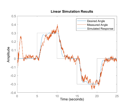
PID Tuning
PID tuning experiments documenting controller adjustment, response behavior, and iterative tuning throughout hardware development.
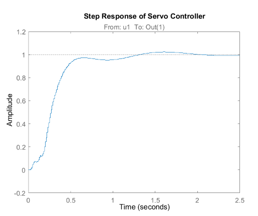
Step Response Validation
Step-response analysis used to evaluate controller stability, overshoot, settling time, and overall dynamic behavior before hardware implementation. This validation helped verify that the controller produced a stable and well-damped response suitable for experimental testing.
Hardware Demonstration
This video shows the bicopter research platform during laboratory testing with my graduate research mentor, Sachin Giri. The demonstration evaluates the experimental control system by introducing external disturbances and observing the platform's ability to return toward its commanded position.
During this stage the prototype was operating on a temporary laboratory power setup, which occasionally interrupted testing before a complete stabilization sequence could be observed. These experiments provided valuable experience with controller tuning, system identification, and validating real hardware outside of simulation.
Video: Experimental bicopter testing conducted with graduate research mentor Sachin Giri and shared with permission. Additional information about his research can be found at sachingiri03.com.np .

conspiracy meme pic bc this is literally me trying to explain how all the bicopter system works and how i put it together XD
Project Outcome
The bicopter project served as my introduction to practical mechatronics research, combining mechanical design, additive manufacturing, embedded electronics, MATLAB/Simulink development, and experimental hardware testing within a university research laboratory. Rather than presenting the project as something I invented from scratch, this portfolio documents how I customized, fabricated, assembled, and documented an existing research platform while gaining hands-on experience with real engineering workflows.
Throughout the project I designed custom mechanical components, manufactured a presentation-quality display stand, integrated electronics, participated in laboratory testing, and explored both open-loop and closed-loop control concepts. Working alongside graduate researcher Sachin Giri provided valuable experience with controller development, troubleshooting, hardware validation, and collaborative engineering research.
This project strengthened my understanding of how CAD design, manufacturing, embedded systems, simulation, and experimental testing support one another during engineering development. It also reinforced the importance of iterative design, documentation, and adapting to unexpected technical challenges throughout a research project.
Skills Demonstrated: CAD Design, Mechanical Design, Additive Manufacturing, Resin Printing, Painting & Finishing, Arduino Integration, MATLAB, Simulink, Prototype Documentation, Experimental Testing, Research Presentation, and Collaborative Engineering.
Inverted Pendulum Platform Redesign
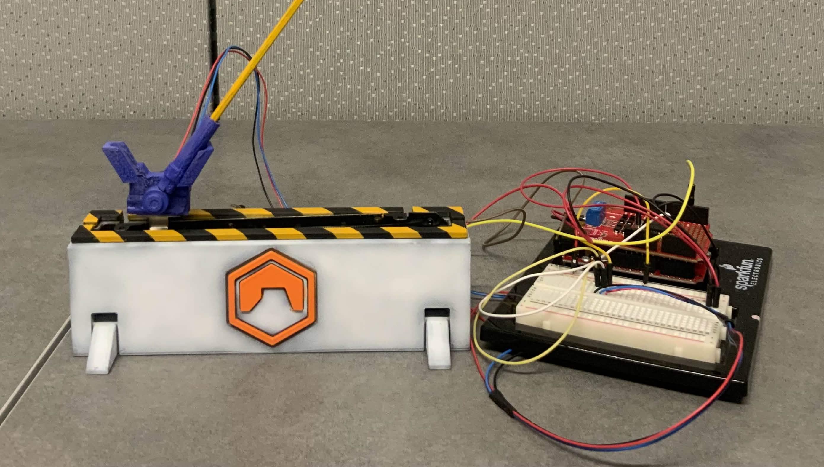
Completed inverted pendulum research platform featuring a redesigned exterior enclosure, integrated laboratory hardware, custom fabrication, painted finishing, and a proposed MATLAB/Simulink PID controller architecture.
Project Overview
This project focused on redesigning and rebuilding an existing inverted pendulum research platform developed in the UC Merced Mechatronics, Embedded Systems and Automation Lab.
The internal mechanism, sensors, motor system, Arduino hardware, and general component arrangement were based on an earlier laboratory prototype. My work focused on studying that platform, rebuilding the physical system, redesigning the external enclosure, fabricating the new housing, integrating the existing components, documenting the development process, and creating a proposed PID controller architecture in MATLAB and Simulink.
Rather than presenting the pendulum as a completely original mechanism, this portfolio documents how I transformed an existing experimental platform into a more polished, futuristic, and presentation-ready research prototype.
My primary contributions: enclosure redesign, mechanical integration, additive manufacturing, fabrication troubleshooting, FDM printing, painting and finishing, physical assembly, research presentation, documentation, and proposed PID controller development.
Original Research Platform
The project was based on an existing MESA Lab inverted pendulum system that used a moving cart, linear position sensing, pendulum-angle sensing, Arduino hardware, motor control, and MATLAB/Simulink communication.
I studied the previous research presentation and system diagrams to understand how the mechanical, electrical, and control subsystems were connected before rebuilding the platform around my redesigned enclosure.
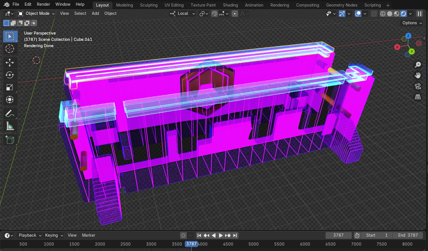
CAD Redesign
A complete CAD redesign of the outer enclosure was created around the existing inverted pendulum hardware. The model preserved the original mechanical interfaces while introducing a new research-style enclosure, mounting features, service access, and an improved visual presentation.
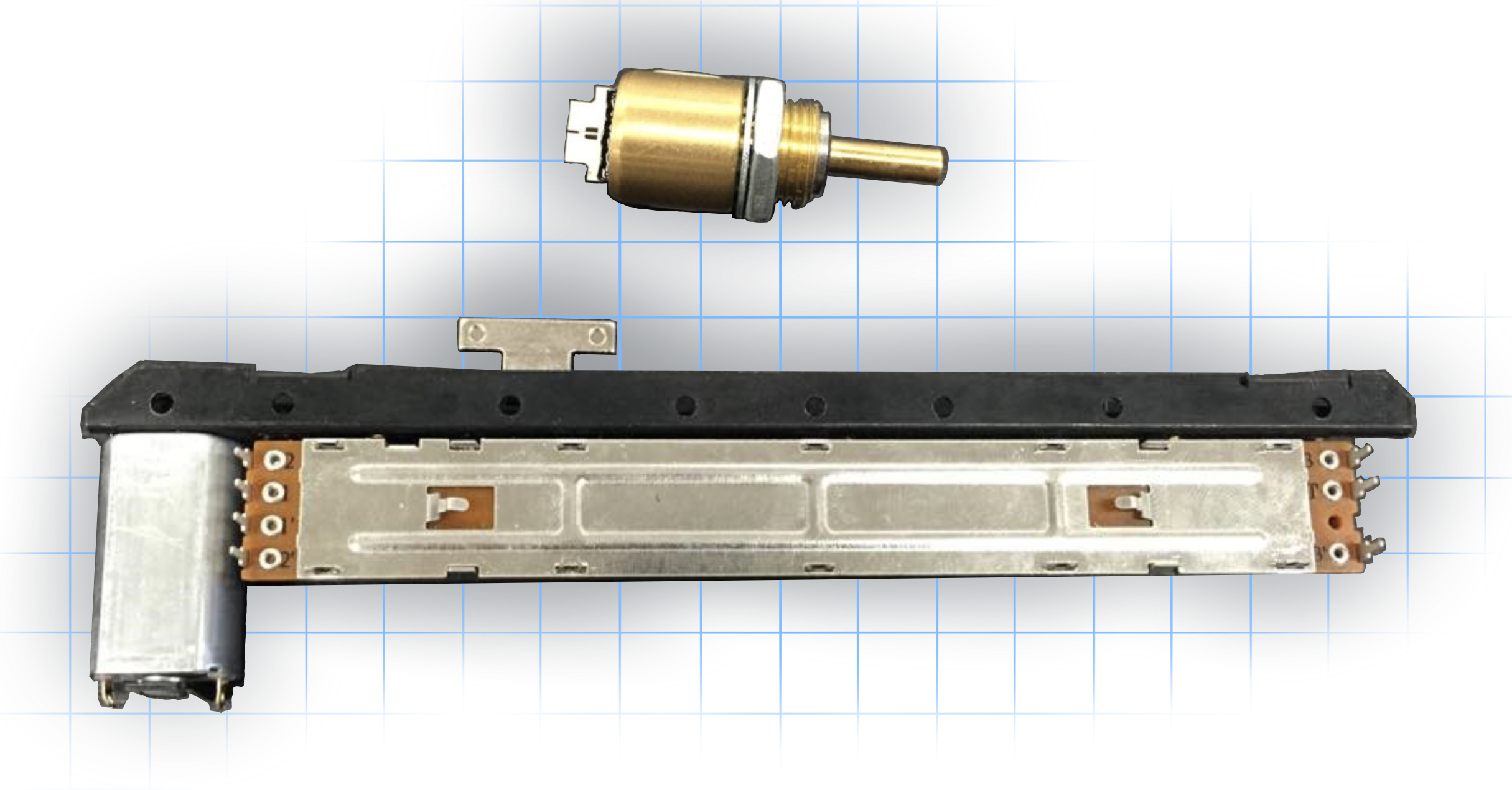
Mechanical Components Reference
Reference illustration showing the moving cart, linear potentiometer, pendulum assembly, and angular-position sensing components used by the existing laboratory platform.
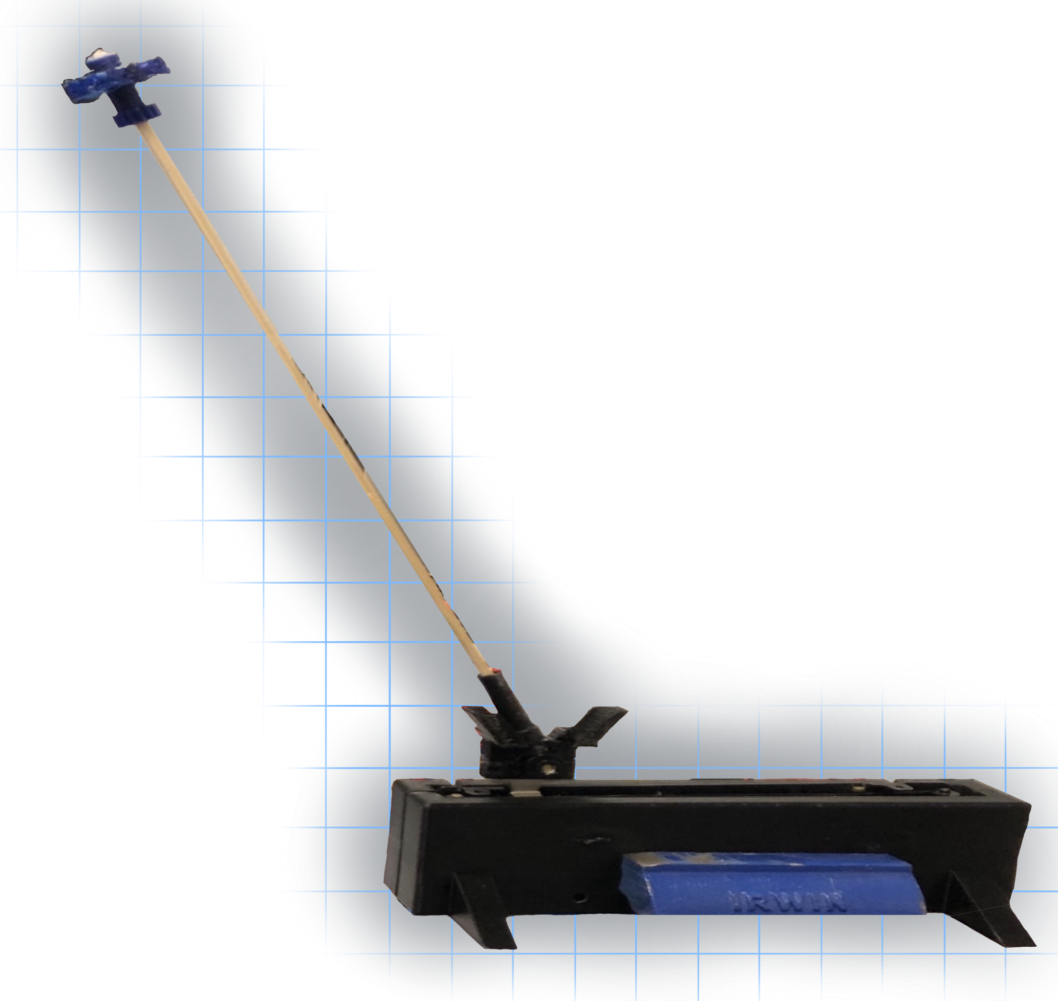
Existing Platform Foundation
The internal mechanism and electronics were based on an existing laboratory platform. My work concentrated on rebuilding, integrating, enclosing, and presenting the system in a more refined form.
Reference diagrams are included only to explain the inherited research platform. They are not presented as my original diagrams or original mechanical design.
Futuristic Enclosure Redesign
The original prototype used a basic rectangular housing that primarily served as a functional container for the internal mechanism. I redesigned the outer structure to give the platform a more intentional research-instrument identity.
The new enclosure was shaped around the existing linear track, moving carriage, pendulum arm, electronics, sensor locations, and wiring access. The redesign introduced a cleaner silhouette, raised structural elements, integrated branding, contrasting color regions, hazard-strip detailing, and a stronger visual relationship between the mechanism and its base.
The goal was not only to make the platform look better. The enclosure also had to preserve access to the internal components, avoid obstructing carriage motion, support the mechanism, and remain practical to assemble.
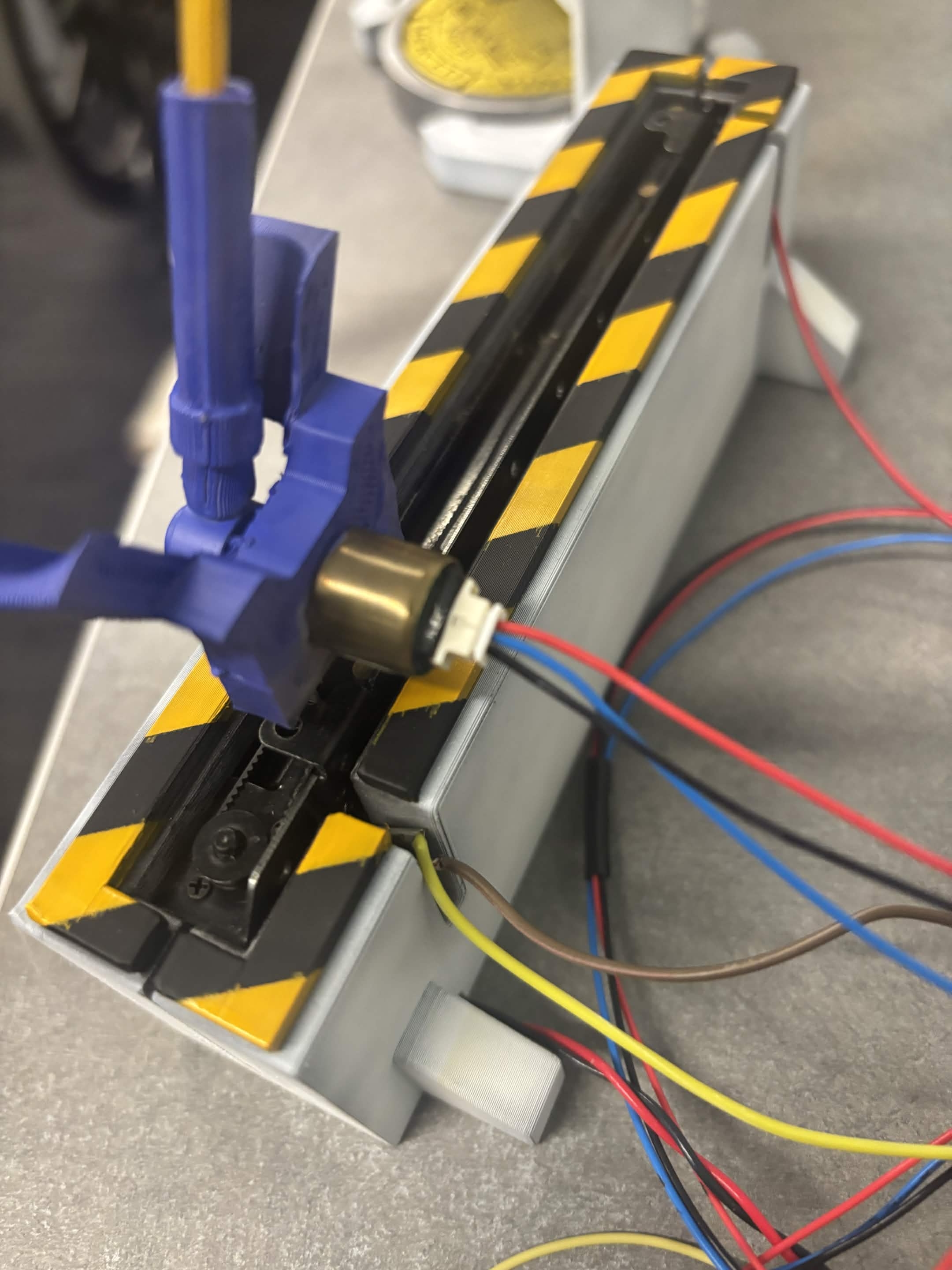
Mechanical Layout Study
Close-up inspection of the linear carriage, pendulum pivot, track, sensor locations, and mounting geometry used to determine the enclosure dimensions.
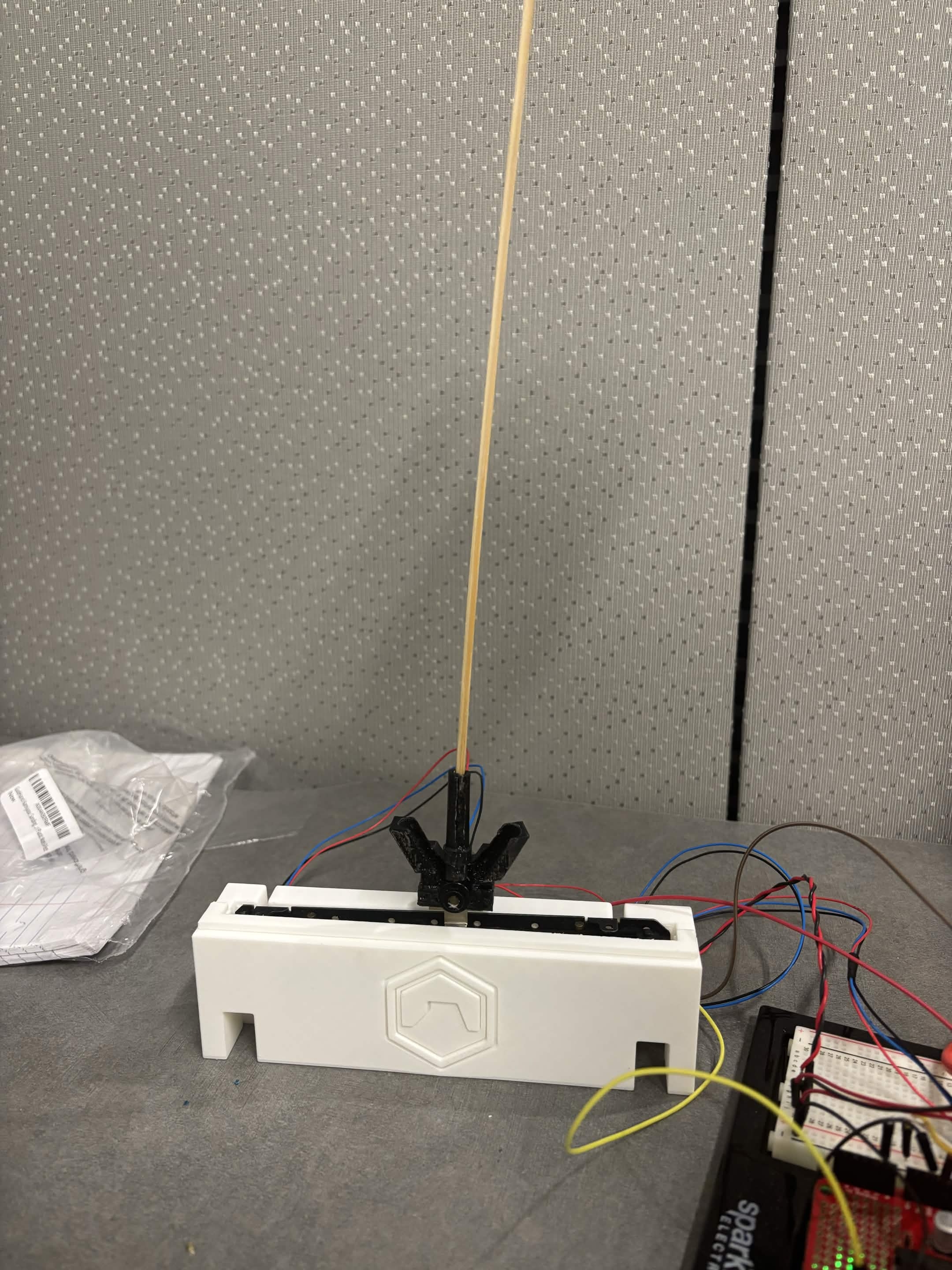
Early Integration Prototype
An early assembly used to confirm component fit, track clearance, pendulum movement, electronics access, and the relationship between the existing mechanism and the redesigned housing.
Finished Enclosure Design
The completed housing replaced the basic original shell with a more futuristic form featuring painted surfaces, integrated MESA identity, structural feet, and hazard-striped upper rails.
Large-Format Resin Printing Attempts
The enclosure was significantly larger than the small armor and model components I normally produced on my Elegoo Saturn 4 Ultra resin printer. Most of my previous prints were only a few centimeters in size, while the pendulum enclosure required a much larger continuous part.
By this stage, the printer had already experienced heavy use from frequent prototype and armor printing. During earlier bicopter fabrication, a resin fragment was missed near the build area. When the build plate returned to its home position, the protective surface and display assembly were damaged.
The bicopter stand had been completed before the failure became severe, but the pendulum enclosure was attempted after the printer had lost most of its reliable usable screen area. Only a limited portion of the display could produce consistent geometry.
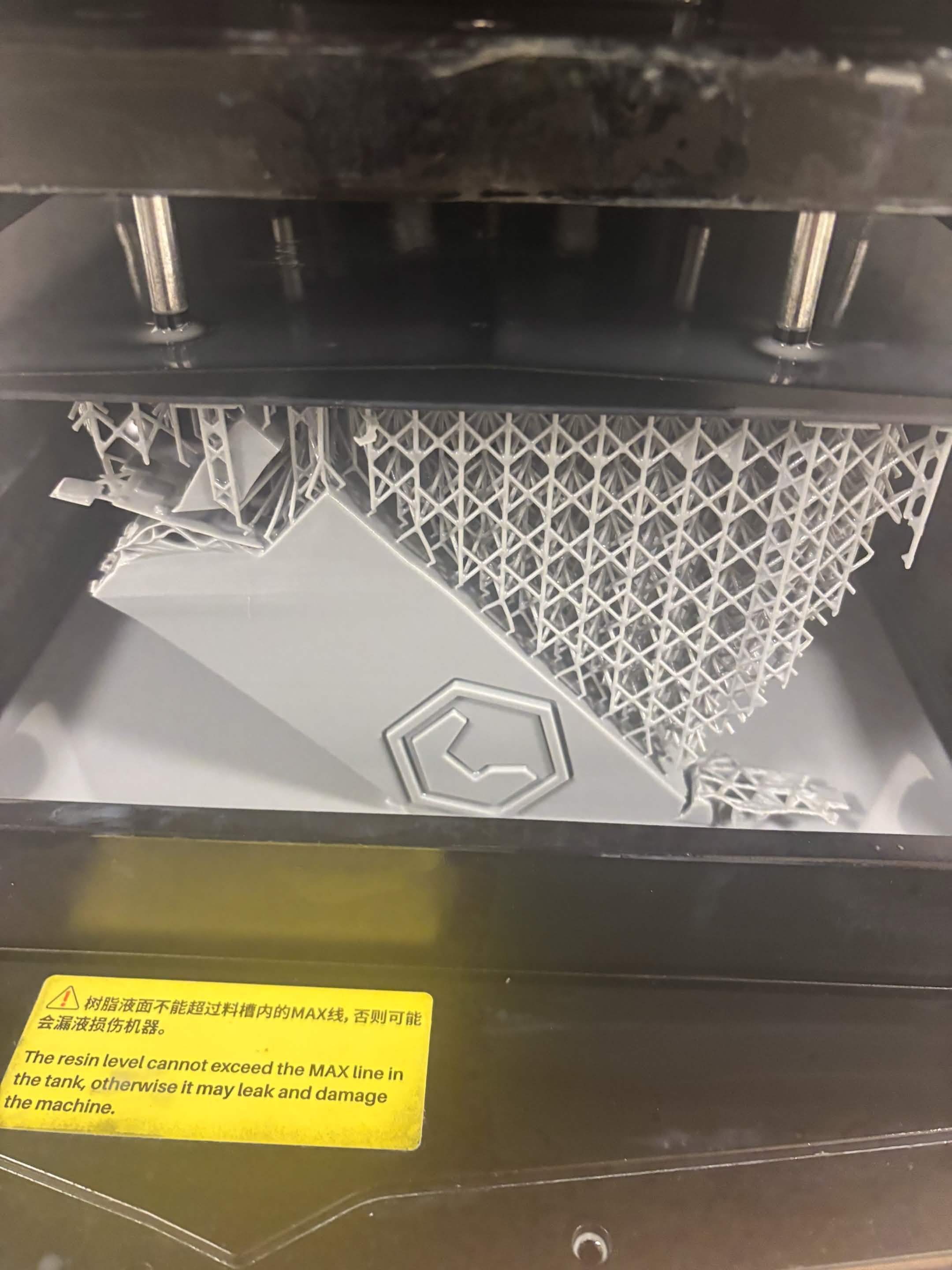
First Resin Attempt
The enclosure was positioned at approximately a 45-degree angle in an attempt to fit the large part within the remaining usable print area. The geometry extended beyond the reliable exposure region and the print failed.
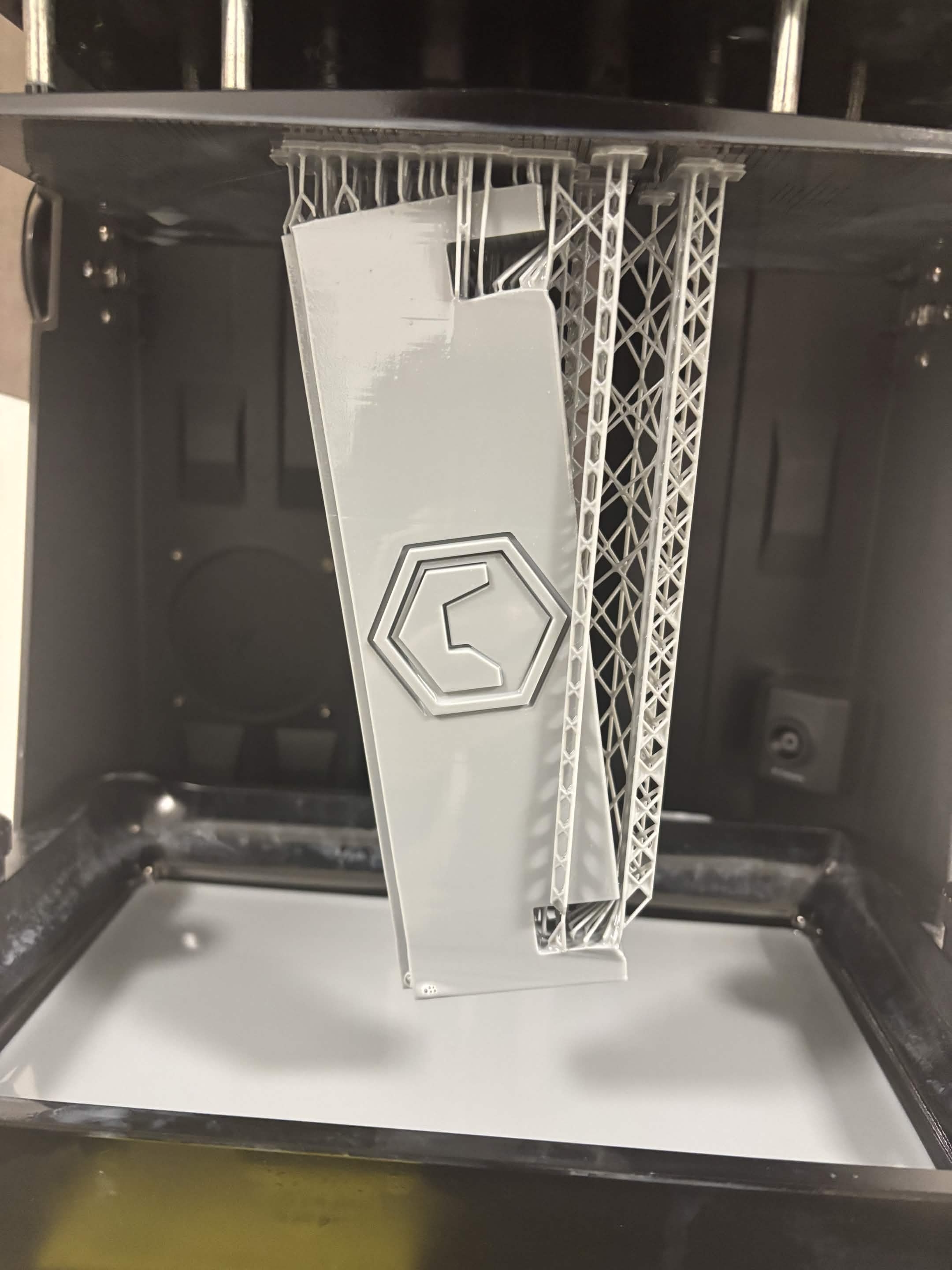
Second Resin Attempt
A second orientation produced more of the enclosure, but the limited display area and uneven exposure caused incomplete geometry and warped outer edges. The part was closer to success but remained unsuitable for the final build.
Fabrication decision: Continuing to repeat the same resin process would have consumed additional material without resolving the damaged screen limitation. The enclosure was therefore adapted for FDM manufacturing instead.
Manufacturing Pivot to FDM Printing
After the resin attempts failed, I moved the enclosure to a Bambu Lab FDM printer. This was not my original preference because visible FDM layer lines and surface inconsistencies become especially noticeable after painting.
However, the FDM printer could reliably produce the full enclosure at the required size. The design was adapted for that manufacturing process, printed in PLA, cleaned, assembled, and prepared for finishing.
The switch from resin to FDM allowed the project to continue despite the resin printer failure. Although the raw surface quality was lower than the original resin target, careful paint application, masking, color separation, and presentation details produced a final result that remained visually cohesive.
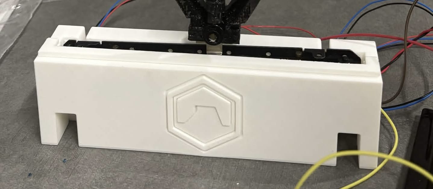
FDM Enclosure Print
The redesigned housing was ultimately produced using PLA after the resin printer's LCD partially failed. Although resin remained the preferred manufacturing method, the enclosure was successfully completed through FDM printing, surface finishing, and painting.
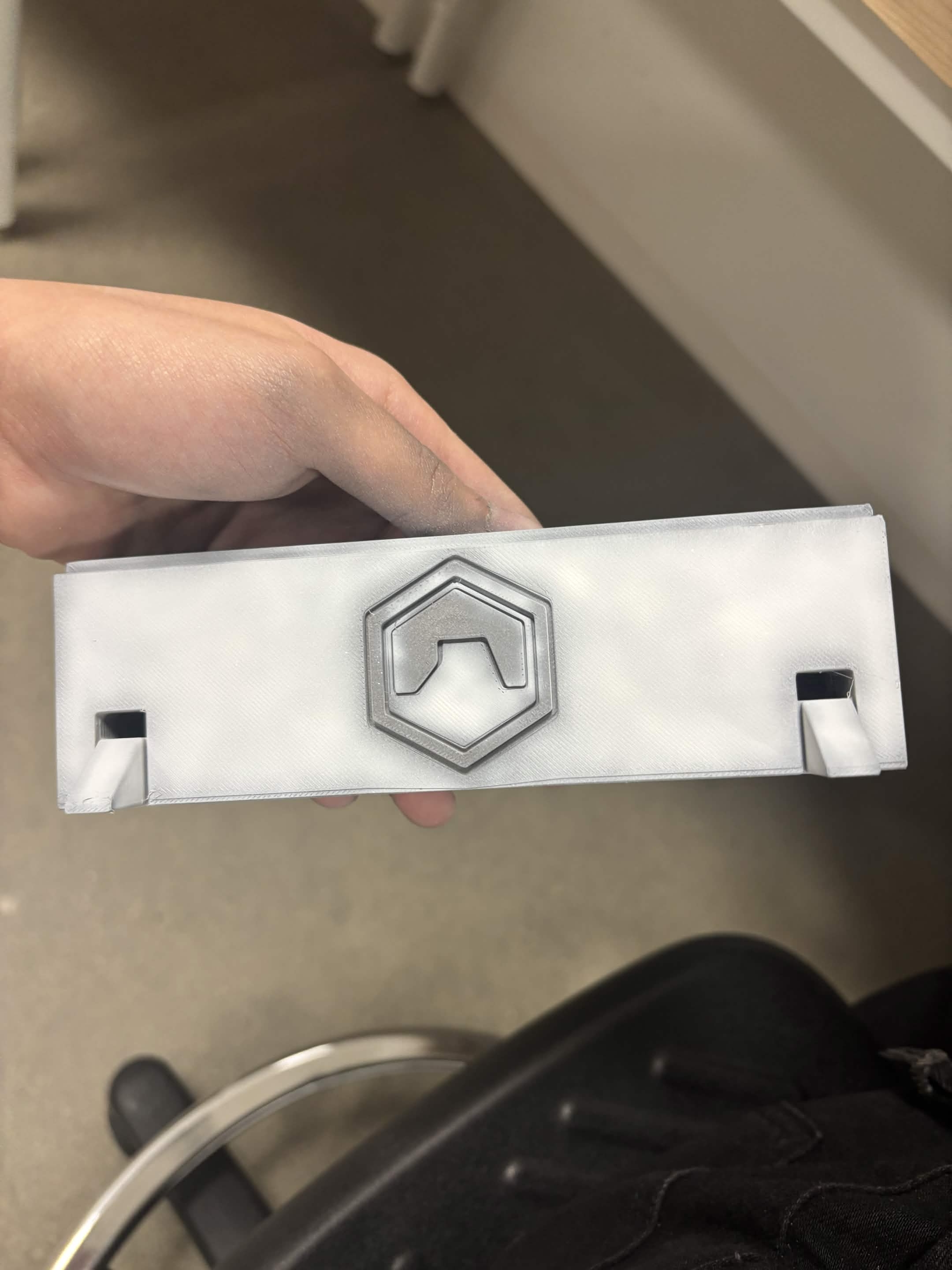
Primer & Airbrushing
The printed enclosure first received a black primer followed by multiple light coats of white airbrushing. The darker edges were intentionally left visible to create depth, improve contrast, and give the enclosure a more industrial appearance before the remaining color accents were applied.
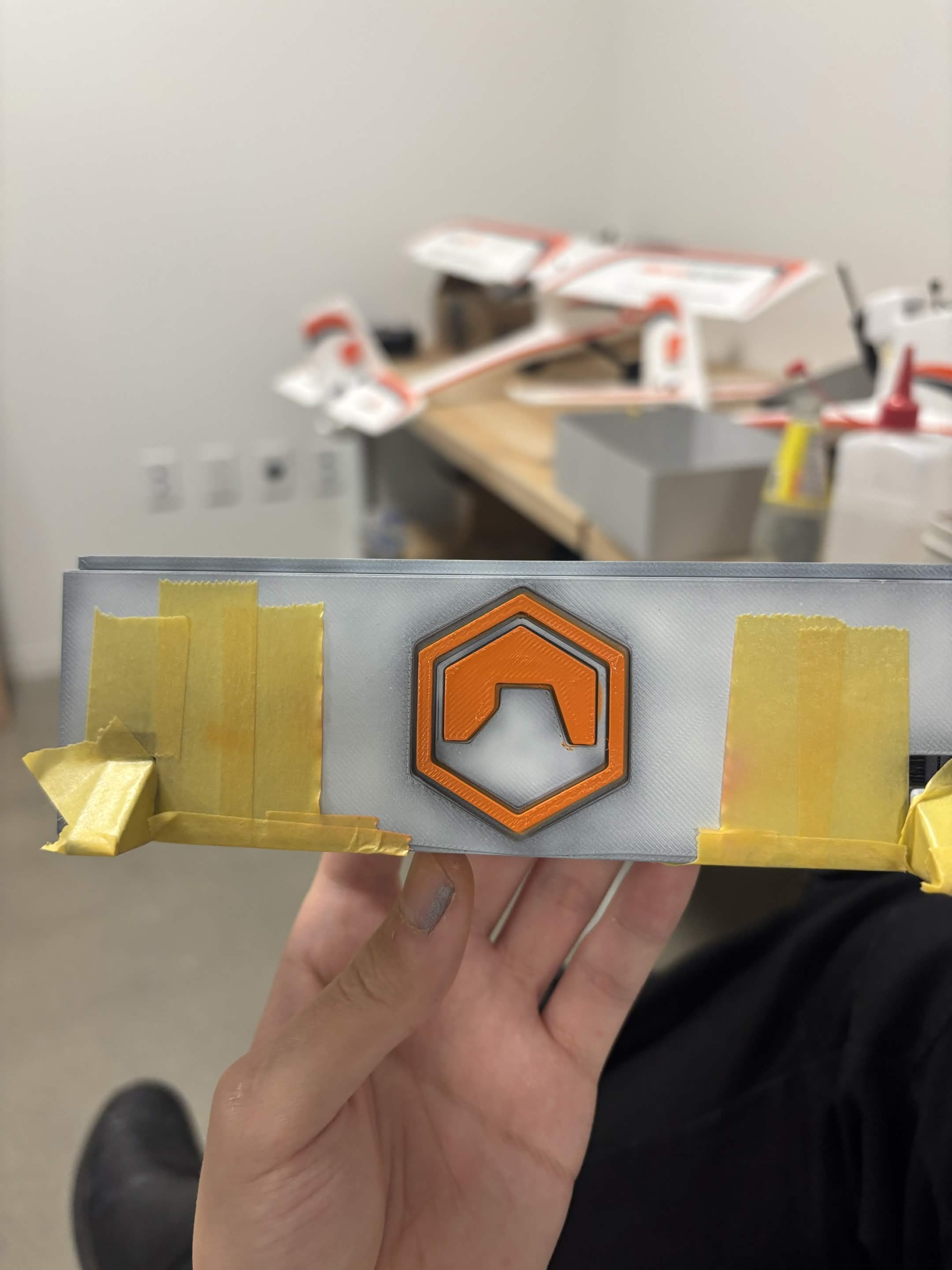
Logo & Detail Painting
The front emblem and smaller accent colors were painted separately to give the prototype a cleaner research identity while helping disguise minor FDM surface imperfections.
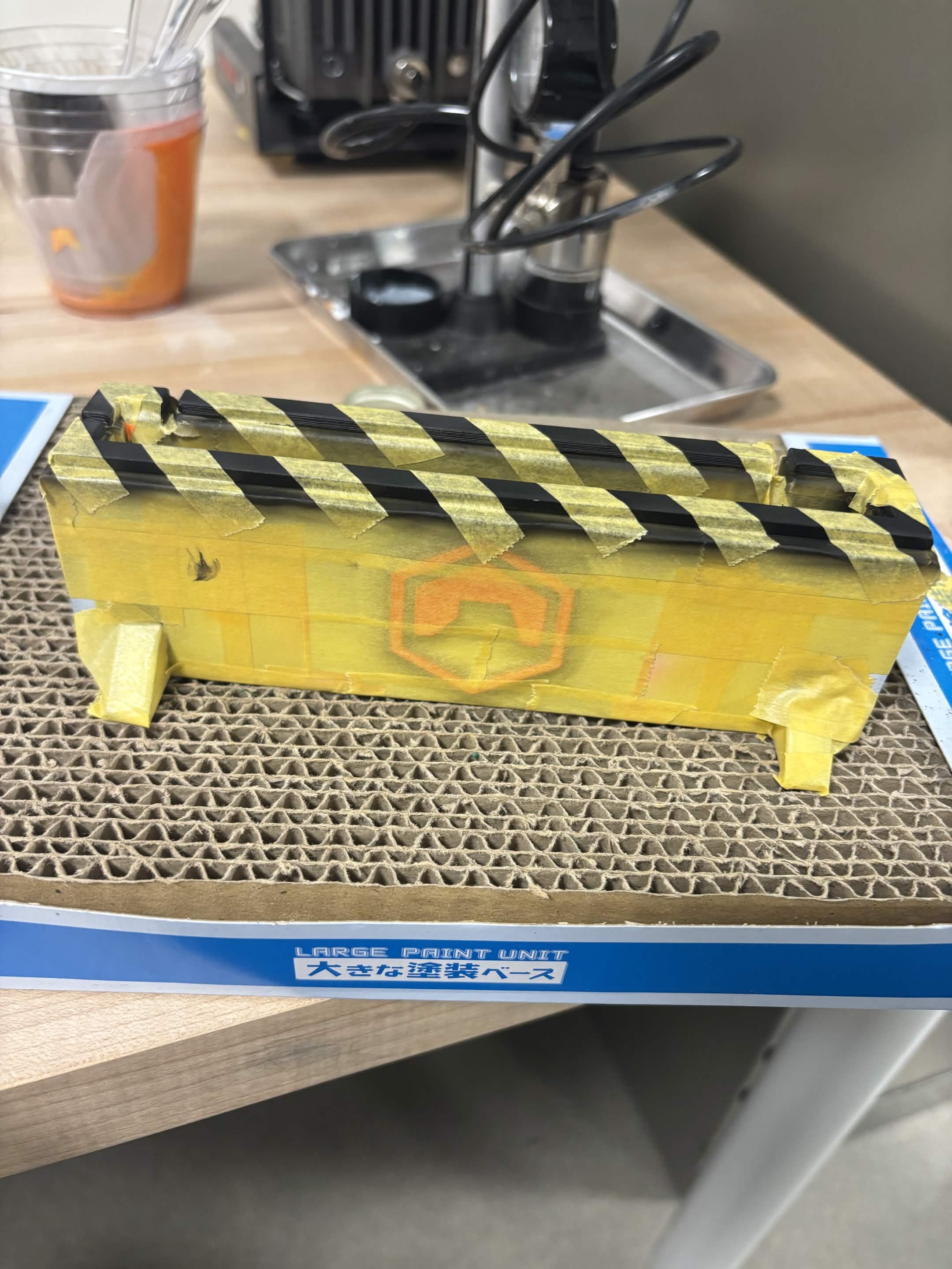
Masking & Color Separation
Masking tape was carefully applied to separate paint regions before the hazard stripes were airbrushed. This process produced clean paint boundaries while protecting the surrounding surfaces during finishing.
Paint Finish Showcase
Rotating showcase of the completed enclosure after painting and finishing. Minor overspray identified during inspection was corrected during a later touch-up, demonstrating the iterative refinement that often occurs during prototype development.
Completed Physical Platform
The finished enclosure was integrated with the existing carriage mechanism, pendulum assembly, electronics, sensors, and wiring to complete the final research platform.
Electronics & Mechanical Integration
The platform combined a linear moving carriage, pendulum-angle sensing, carriage-position sensing, motor actuation, Arduino hardware, motor-control electronics, and MATLAB/Simulink communication.
Because the electronics had already been developed for the existing laboratory platform, my work focused on understanding the system, redesigning the enclosure, integrating the hardware, and presenting the prototype as a cleaner and more professional engineering platform while developing my own controller architecture.
Integrated Experimental Platform
The completed setup combined the redesigned enclosure, moving carriage, pendulum arm, sensors, Arduino interface, motor-control hardware, and external wiring.
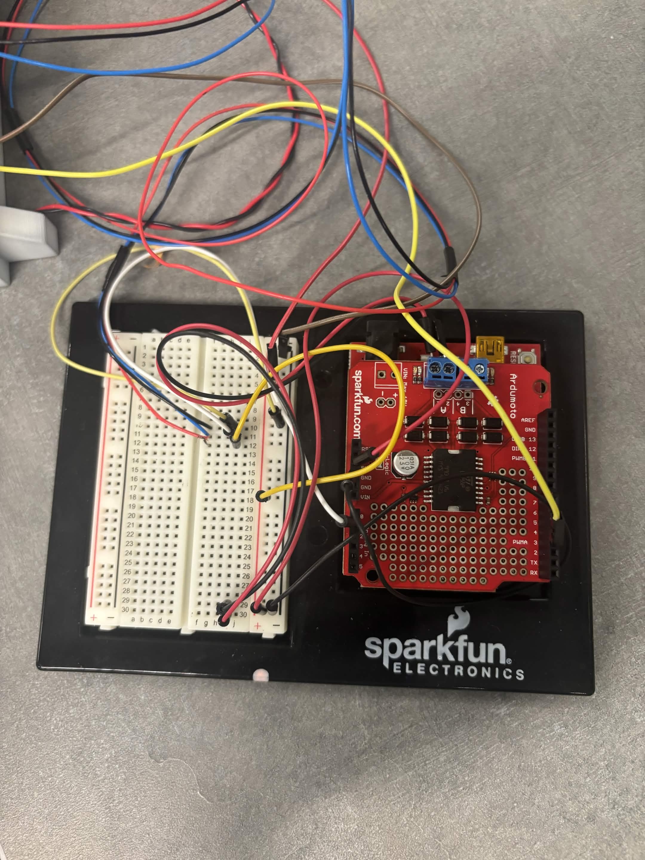
Arduino Electronics
Top-down view of the Arduino Uno, motor driver, breadboard wiring, and supporting electronics used during hardware integration and controller development. The electronics remained accessible during testing to simplify wiring changes, troubleshooting, and controller development.
Position & Angle Sensing
Reference illustration showing the moving cart, linear potentiometer, magnetic angle sensor, guide rail, and pendulum mechanism used by the inherited laboratory platform.
MATLAB, Simulink & Proposed PID Controller
After studying the existing laboratory control architecture, I developed my own Simulink controller model for the rebuilt platform. The design built upon the original research workflow while adapting it to my intended hardware configuration.
The proposed controller removed the Bluetooth communication stage and instead focused on direct MATLAB, Simulink, and Arduino integration. It organized PID position control, dead-zone compensation, cart-position input/output, and pendulum-angle sensing into a single control architecture for future hardware implementation.
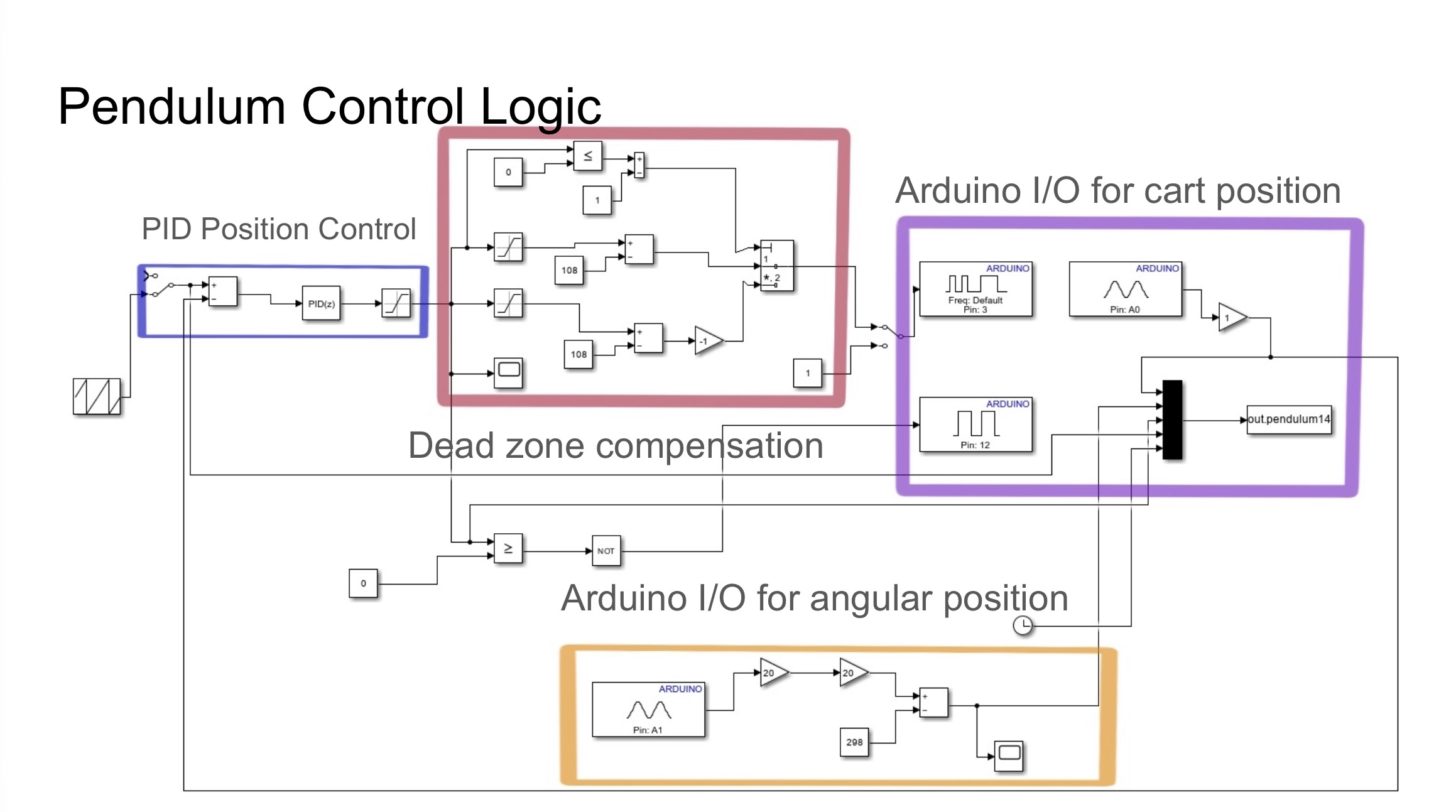
Proposed PID Controller
My proposed Simulink controller architecture combined PID position control, dead-zone compensation, and Arduino communication into a unified workflow. Although the controller was not fully deployed before the end of the research period, it documents the intended direction for future implementation.
Implementation Status
The controller architecture was created near the end of the semester. By that stage, enclosure redesign, fabrication setbacks, the transition from resin to FDM printing, finishing, and hardware integration had already consumed much of the remaining project schedule.
Full deployment required additional work on signal scaling, sensor interpretation, Arduino data types, motor dead-zone behavior, actuator limitations, and safe testing of the unstable physical system.
The PhD researcher and faculty advisor were also occupied with final examinations and end-of-semester responsibilities. As a result, the proposed PID model was not implemented or experimentally validated on the physical prototype before the research period ended.
Completed: platform study, enclosure redesign, fabrication attempts, manufacturing-process change, FDM production, painting, assembly, hardware integration, documentation, and proposed PID architecture.
Not completed: final controller deployment, closed-loop balancing, response measurement, PID tuning on hardware, and experimental step-response validation.
For this reason, the portfolio does not claim successful stabilization or include fabricated response graphs. The controller is presented accurately as a proposed design prepared for future implementation.
Engineering Lessons Learned
This project demonstrated that engineering progress does not always follow the original plan. A design may be mechanically sound while the selected manufacturing process becomes unavailable. A controller may be logically structured while still requiring significant embedded implementation and hardware-validation work.
The printer failure forced me to evaluate the remaining equipment capability, recognize that repeated resin attempts were unlikely to succeed, and move the project to a different manufacturing process. The final result was not the surface finish I originally planned, but it allowed the prototype to be completed and presented.
The control work similarly showed the difference between understanding a diagram and deploying a controller on an unstable physical system. Sensor noise, actuator saturation, dead zones, timing, signal scaling, mechanical friction, and software compatibility all become important once simulation must interact with real hardware.
Most importantly, the project reinforced my strongest engineering interests: mechanical integration, additive manufacturing, prototype recovery, engineering visualization, enclosure design, physical presentation, and the connection between technical hardware and visual communication.
Research Platform Demonstration
This demonstration shows the original MESA Lab inverted pendulum platform maintaining balance while responding to external disturbances. The balancing controller shown in the video was developed during earlier laboratory research and served as the foundation for my study of the system.
My work focused on redesigning the enclosure, adapting the hardware for a new manufacturing process, integrating the existing electronics, documenting the engineering process, and developing a revised Simulink PID controller architecture for future implementation.
Video: Existing laboratory platform demonstrating stable closed-loop balancing under external disturbance.
Project Outcome
This project demonstrated that engineering is often an iterative process rather than a straight path from concept to completion. While the original laboratory platform provided the mechanical foundation, I redesigned the external enclosure, adapted the system for a new manufacturing process after multiple resin-print failures, integrated the hardware, documented the development process, and proposed a new Simulink controller architecture for future implementation.
Although the controller was not fully deployed before the end of the research period, the completed platform represents a successful combination of mechanical redesign, additive manufacturing, hardware integration, and engineering communication. The experience strengthened my understanding of how mechanical design, embedded systems, and control theory come together in real-world mechatronics projects.
Research Manuscript
I was listed as a co-author on an inverted-pendulum control manuscript titled A Systematic Design of A Dual-loop PID Controller for An Inverted Pendulum on A Moving Cart. The manuscript lists Shiang Cao, Sachin Giri, Kenneth Furrer, and YangQuan Chen as authors.
A PhD researcher from the lab informed me that the paper has been published and should become publicly available online. Until I can verify the final publication record, DOI, conference listing, or indexing page, I am labeling this section as a research manuscript / publication pending online record.
I include this carefully and transparently. I do not present the control-theory analysis as my own primary work. My portfolio evidence remains focused on the hardware, fabrication, resin printing, mechanical presentation, assembly, photography, and prototype documentation I personally completed.
Status: Publication reported by lab contact; public link / DOI / indexing record pending verification.
How I use it: Documentation of research affiliation and lab context, not a claim that I led the technical control-theory study.
My strongest documented contributions: hardware fabrication, prototype display work, resin-printed components, mechanical presentation, assembly, photography, and project documentation.
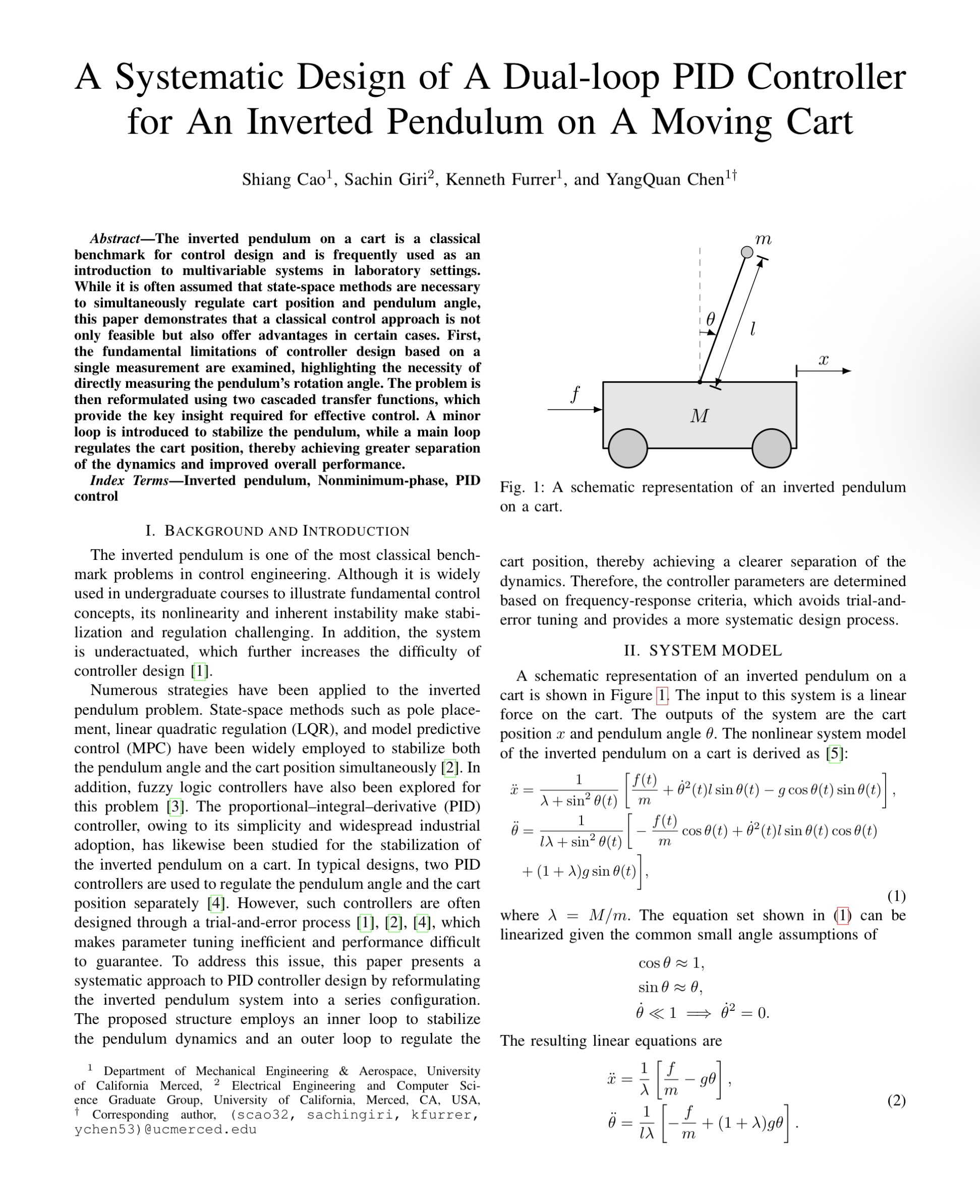
Manuscript Title Page
Add a screenshot of the first page showing the title and author list.
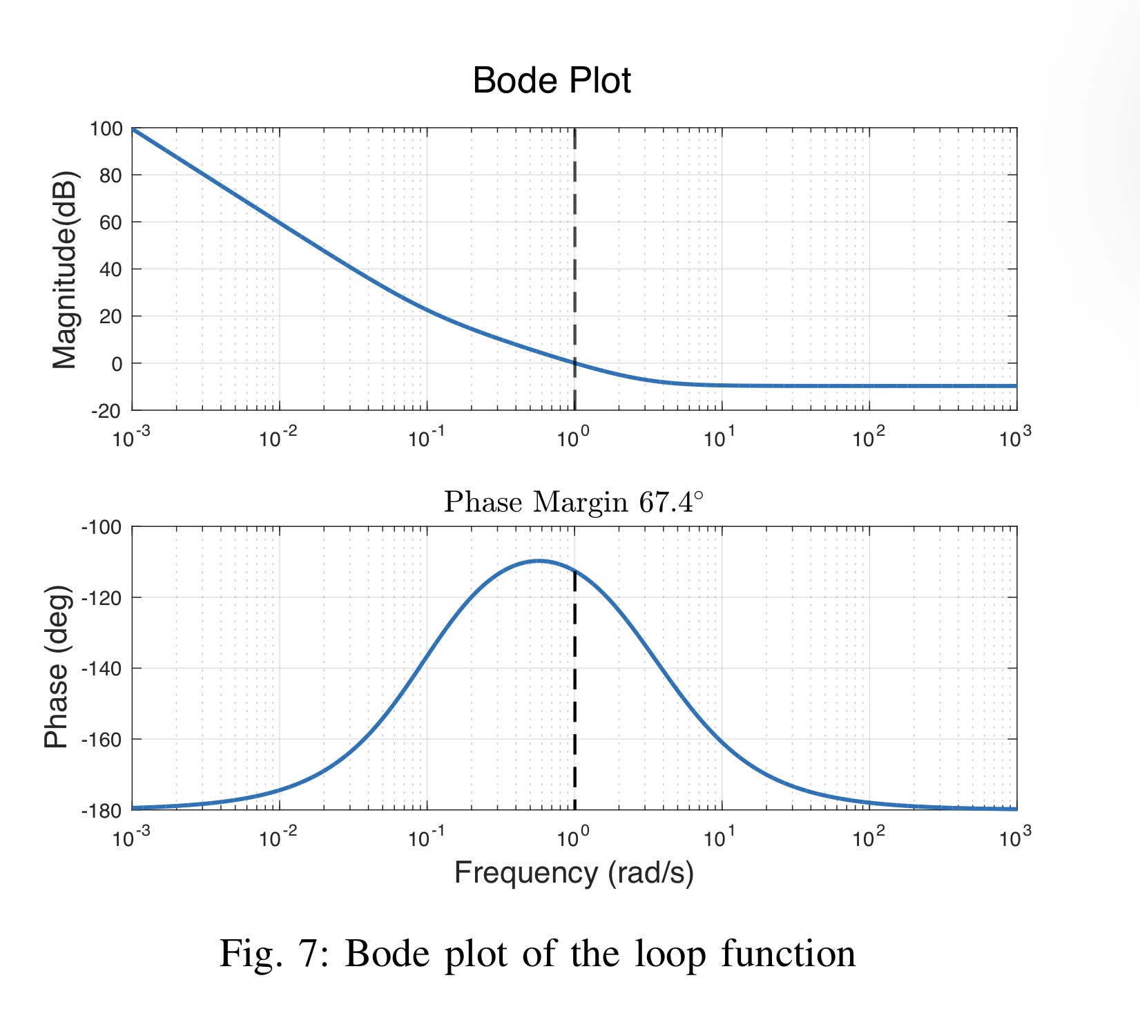
Control Study Context
The manuscript discusses dual-loop PID control, inverted pendulum dynamics, frequency response, and simulation results.
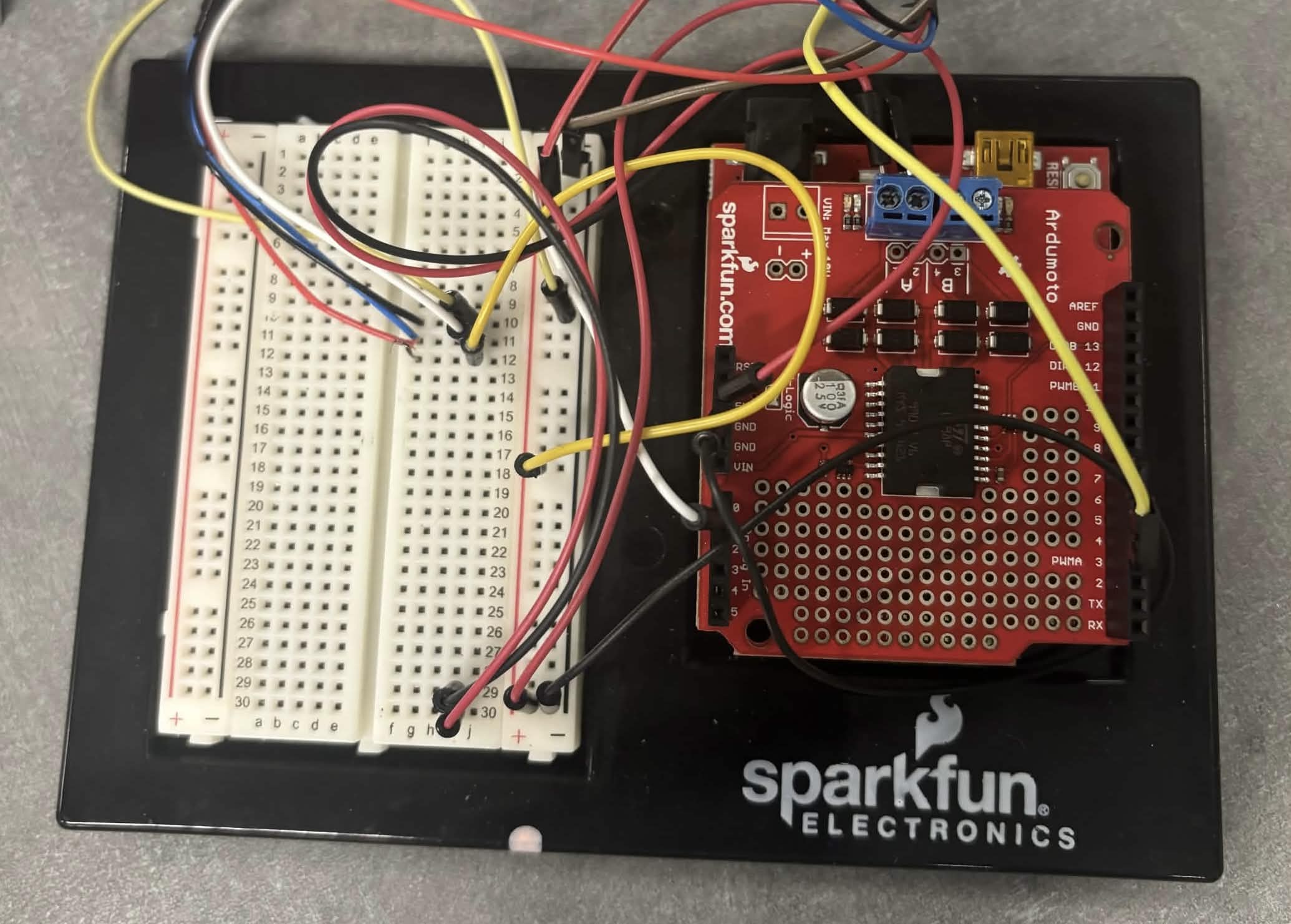
Existing Laboratory Platform
Photograph of the laboratory electronics used by the inverted pendulum research platform. The hardware architecture originated from prior work in the MESA Laboratory and served as the foundation for my enclosure redesign, mechanical integration, fabrication, documentation, and development of a proposed MATLAB/Simulink controller architecture.
Reflection
These projects showed me that successful engineering is rarely the work of one person. Each prototype grew from faculty guidance, graduate research, open-source foundations, existing laboratory systems, and many rounds of testing, discussion, and iteration.
My strongest role was transforming complex laboratory hardware into polished, well-documented prototypes through CAD, additive manufacturing, fabrication, mechanical integration, painting, presentation, and controller development. That work taught me how mechanical systems, electronics, software, controls, and visual communication support one another throughout engineering development.
I hope to bring this combination of engineering, fabrication, and visualization to multidisciplinary teams developing robotics, aerospace systems, advanced manufacturing technologies, and other products where thoughtful design and clear communication are essential.